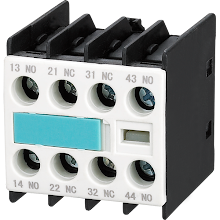
Through contacts whenever a relay is used to switch a large amount of electrical power, it is designated by a special name: ac contactors. Contactors generally have multiple contacts, and those contacts are usually open so that when the coil is de-energized power to the load is shut off.
Control of electric motors is the most common industrial use for contactors
The respective phases of the incoming 3-phase AC power; typically at least 480 Volts for motors 1 horsepower or great are switched by the top three contacts. An auxiliary contact is the lowest contact which when compared to the large motor power contacts has a current rating much lower, but like power, contacts are actuated by the same armature.
In a relay logic circuit the auxiliary contact is frequently used, or for another part of the motor control scheme, typically switching 120 Volt AC power instead of the motor voltage. One central air contactor may have There are several auxiliary contacts in one contactor, either normally open or normally closed if required.
Three-Phase Electric Motor Contactor
For a three-phase electric motor here is a contractor that at a municipal water treatment plant is installed on a panel as part of an electrical control system:
Sample Contactors
At the top of the split ac contactor that too with the help of screw terminals labeled L1, L2, and L3, three-phase, 480 volt AC power comes into the three normally-open contacts. At the bottom of this device via screw terminals labeled T1, T2, and T3, power to the motor exits the overload heater assembly.
The overload heater units are generally black, square-shaped blocks with the label W34. For a certain horsepower and temperature rating of the electric motor, it indicates a particular thermal response.
The overload heater units must be replaced with units having a thermal response suitable for the new motor only when an electric motor of differing power or temperature ratings. On the appropriate heater units that need to be used, the motor manufacturer can provide information.
In
manually resetting the normally-closed switch contact back to its normal state
a white push-button located between the T1 and T2 line heaters is used. Follow us on Facebook


No comments:
Post a Comment