Monday, 23 January 2023

Know About the Use of Contactors

An electrical device called a contactor, such as a magnetic contactor, is frequently used to turn circuits on and off. As a result, electrical contactors are an electromagnetic switch's relay sub type.


In a variety of circumstances when it is necessary to frequently switch power to a circuit, an electrical contactor is employed. They are created and manufactured to carry out this function across a huge number of cycles, just like relay switches.


magnetic contactor

More often than relays, contactors are used in applications requiring more power. This is due to their capacity to turn, or "power cycle," a circuit with much larger voltages and currents on and off using low voltages and currents.


A contactor is often utilized when power loads need to be switched on and off quickly or frequently. They may, however, also be set up so that power is either turned on or off to a circuit when it is engaged.


The two traditional uses for magnetic contactors are as electric motor starters (such as those used in electric cars that require auxiliary contacts and connections) and in high-powered lighting control systems.


magnetic contactor

A contactor will often offer several additional safety features when it is used as a magnetic starter for an electric motor, including power-cutoff, short circuit protection, overload protection, and under-voltage protection.


To reduce total power usage, latching configurations of contactors are frequently employed to regulate high-power lighting systems. In this configuration, two electromagnetic coils cooperate. When temporarily charged, one coil will close the circuit connections and maintain them magnetically closed. When activated, the second coil will reopen them.


Large-scale office, commercial, and industrial lighting automation is a popular use for this kind of arrangement. The operation is similar to that of a latching relay, however, the latter is more frequently utilized in circuits with smaller and lighter loads.


Electric contactors are often bigger and more durable than normal relay-switching devices since they are designed particularly for these kinds of high-voltage applications.


However, the majority of the electric contactor is still made to be quickly mounted and portable, and they are typically seen as being excellent choices for usage in the field.


Follow us on Facebook

Friday, 20 January 2023

Know About the Working of Voltage Regulators

Any electrical circuit or device needs a voltage regulator to keep a continuous yet steady amount of voltage flowing through it. In other words, these regulators ensure that the proper quantity of electricity or power is always directed toward the proper locations. Electrical equipment wouldn't function correctly without them.


There are many different types of voltage regulators available, and while they all manage the continuous flow of electricity, they all do so differently and for various reasons.


voltage regulator


Voltage regulators can be found in integrated circuits, electromagnetically devices, or solid-state automated regulators, depending on the physical architecture. Integrated circuits with basic transistor-based linear regulators are regularly produced (ICS). The internal circuitry of differential amplifiers controls output voltage about a reference value.


The output of a linear automatic voltage regulator can be fixed or adjustable. Typically, they require an input current equal to the output current.


The two most common subcategories of active voltage regulators are linear and switching regulators.


By switching a series device on and off, high-frequency switching regulators alter the output voltage's duty cycle. They typically employ the typologies of buck, boost, and buck-boost. Buck converters may still step up the output current while being more effective during voltage step-down.


voltage regulator


It is crucial to know the voltage regulator to employ for the work at hand; else, you risk failing to complete it. Passive and active regulators are the first two major categories of regulators that you should be familiar with. Make sure you utilize an active regulator if the power circuit requires higher voltage or power.


Active regulators may raise the voltage and are a little more complicated. When adequate voltage is already being supplied, passive regulators are often used to simply discard any excess voltage, maintaining the same amount of power. Passive regulators do not raise the voltage.


You need a mains regulator to regulate the wattage if you're working with AC power lines. The correct energy tap is found and used by mains automatic voltage regulators to power a transformer. Simply said, if the juice from the tap is too high, this device selects a lower juice tap and vice versa. Use a coil rotation AC regulator to assist in controlling wattage or volts. To lower or raise voltage, this gadget rotates a coil.


Follow us on Facebook

Monday, 19 December 2022

Why Does Your Circuit Breaker Burst Sometimes?

We must first comprehend the definitions of overload, short circuit, and earth leakage to comprehend what causes an air circuit breaker to trip (more frequently known as the burst).


How Do Circuits Work?


Circuits are the electrically distinct sections that make up the electrical installations in our houses. Each circuit supplies electricity to a very narrowly focused collection of devices. One circuit known as the lighting circuit contains all of the light fixtures and light switches. On a separate circuit known as the HVAC circuit, air conditioners, heaters, and ventilation devices are grouped. Additionally, on a circuit known as the power circuit, socket outlets are grouped.


ac breaker


Cables, switches, connectors, and other electrical components are all a part of every circuit and are built to only carry the maximum electrical current recommended by the manufacturer. The electrical component may malfunction, melt, or catch fire if it is subjected to current levels that are higher than this limit. When the electrical current flowing surpasses the maximum capacity that the circuit components can tolerate, the circuit dc breaker cut off the electricity supply to prevent this from happening.


The primary cause of circuit breakers tripping is overloaded circuits.


Check out all the socket outlets in your home. How many devices are connected to each outlet and socket? You most likely have more than the circuit is intended to handle. Our electrical infrastructure is under increased stress every day as a result of the growing number of electrical and electronic gadgets we use, sometimes to the point where the quantity of power we consume surpasses the maximum that the circuit can provide without overheating or breaking. Your switchboard's circuit breaker will cut off the circuit from the electrical supply when this happens.


ac breaker


Short Circuits: When Everything Goes Bad


Direct contact between the cable's wires happens when you drill a hole in it or cut it with a spade. We call this a short circuit. Electrical wires aren't made to sustain the amount of electricity that would flow in such a short circuit. To prevent the cable from melting or catching fire in situations like this, the ac breaker short-circuits prevention system cuts off the electrical supply.


Follow us on Facebook

RCDs: Everything an Electrician Must Know

A residual current device that uses residual current is highly susceptible to harm from vibrations, low temperatures, and dusty or moist environments. After being closed for a very long time, they may drastically alter the tripping threshold. As a result, international standards mandate that residual current devices undergo more thorough testing than over current protection devices regularly.

rccb

A Residual Current Device is a sensitive safety device that, in the event of an electrical accident, immediately turns off the power. An RCD is made to guard against the dangers of fire and electrocution brought on by the earth's faults.

Circuit breakers may be put in your home, but they only guard against overloading and short circuits, not electrocution.

How do RCDs function?

Every three months, the test button on an RCD should be depressed to mimic a malfunction and determine whether the RCD is functioning properly. After each test, you might need to reset your electric clocks and timers.

Every day when they report to work, electricians give it their all, and we always aim to leave a project in a safer condition than when we arrived. But what if, despite our best efforts, we unintentionally contributed to the situation getting worse?

rccb

Both the current-operated form, also known as a residual current device (RCD), and the even older voltage-operated kind of earth leakage circuit breaker (ELCB), were historically recognized by BS 7671. The only recognized and utilized kind now is the current-operated type.

The following words were used to describe ELCB devices:


  • indirect contact protection, also known as fault protection
  • additional defense against direct impact, now known as fundamental defense
  • protection against heat and fire as well as added protection
The wiring, fixed appliances, and people utilizing the installation are protected by these devices, which are mounted within an electrical system unit. Monitoring the electric current passing through one or more of the circuits that an RCD is meant to safeguard ensures protection. The risk of death, injury, or fire is decreased if the RCD detects electricity traveling down an unauthorized channel, such as through a person or a malfunctioning appliance, and down to the ground. A device that keeps track of incoming and outgoing current flow trips when there is an imbalance. You can buy rccb online.

Follow us on Twitter

Saturday, 26 November 2022

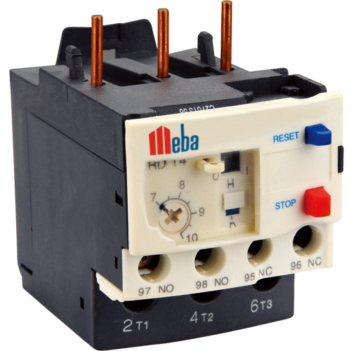
Guide on Working Principle of Thermal Overload Relay

A thermal overload relay is a safety device used in manual control circuits. The thermal overload shuts off the heating circuit using an electric motor to control its overheated short circuit when the temperature exceeds the specified threshold. The thermal overload relay will be used if there is a danger of a short circuit or if there are consistently high temperatures in the area where it is positioned.


A thermal overload relay is a type of relay used to guard against overheating in electrical circuits. To keep the motor going, it recognizes when the current has grown enough and opens rather than switching off the circuit's electricity.


overload thermal relay

A thermal overload relay has two contacts, one of which is often open and the other of which is typically closed, to effectively carry out its functions. In this article, the operation of a thermal overload relay will be described.


A relay for overload


An overload relay, a safety device, protects your circuit from damage caused by high-power loads. The relay opens to protect the circuit when the load reaches a certain threshold.


The simplest sort of overload relay switch is a single-pole, single-throw (SPST) switch. This type of relay only has one fixed position and responds to input signals from the load or source with a single step.


overload thermal relay


Before employing a relay, you must first be aware of the type of circuit you are protecting. For instance, it will be far safer to utilize a relay rather than a second tripping switch close to where the cook top cable links to the power cord if you have an electric stove top.


Consider a plug that has many circuits going through it. In that situation; you may also utilize overcurrent protection devices, such as overcurrent fuses or shutters, to safeguard certain circuits against harm brought on by an overload of current from other circuits coming into touch with them at the same time.


According to the concept of thermal expansion, the overload thermal relay is dragged out of the mounting base as it senses a temperature rise and expands. Push-on contacts that close when connections are withdrawn are therefore liberated.


Follow us on Twitter

Friday, 25 November 2022

Electronic Temperature Controllers of New Generation

The modern electronic temperature controller outperforms mechanical and electromechanical thermostats as well as conventional thermal solutions. Remote temperature sensors that can detect temperatures up to 400 feet away are the main component of their innovation. The user may pick set point temperatures and alter temperature settings using the usual digital display and keypad that come with them. Additionally, the electronic temperature controller has diagnostic tools that look for issues with the hardware, operating system, and software.


It also has a surprising number of functions, such as multiple voltage inputs, adjustable heating/cooling modes, and large temperature ranges. The prewired type, which may be used in incubators and aquarium chillers, is still included in this class. The ease of installation and usage of the aforementioned gadgets is their main benefit.


temperature controller pid


To install them, all that is required is one finger. These are exact since the barometric pressure does not affect how they regulate temperature controller pid. Together, tight differentials and a small tolerance contribute to this precision. Their usefulness is improved by their low energy consumption and extra built-in timers.


Micro-controls and microprocessors have also been used for the first time in electronic temperature controllers. All of these are utilized by digital temperature controls to manage heat. The majority of these digital temperature controls are micro controller-based.


temperature controller pid


These consist of basic digital thermometers used in chilling facilities, furnace control, and labs. For police protection, we also provide digital linear zed temperature indicators and controls. Digital portable thermometers are also available for industrial usage, monitoring the temperatures of liquids, grains, powders, and gases. Temperatures of vibrating surfaces are also measured. Pid temperature controller, which is used to regulate process parameters against time, is another type of digital device.


Another gadget that is based on a micro controller is a digital counter. This semi-conductor counter is used to keep track of how many times a digital event has taken place. Other significant devices incorporating micro-controllers are ramp soak controllers. They regulate the temperature rise and then keep it there for a predetermined period known as the soak time. They have programmable temperature increase rates, PID control algorithms, and a dual display showing set point and current temperatures.


Follow us on Twitter

Saturday, 29 October 2022

Energy Meters of the Electromagnetic Induction Kind

 A digital kwh meter is simply a tool or gadget used to gauge how much electricity is being utilized by a load or a customer. Domestic, commercial, or industrial loads are all acceptable. Watt is the SI unit for electrical power. For this device the watt-hour (Wh) meter is one another name. These electricity meters are deployed anywhere a utility company provides electricity. The load and energy meter are always linked in series. The load will either be single-phase or three-phase, and the energy meter will either be a single-phase meter or a three-phase meter depending on the kind of load.

kwh meter 3 phase

In essence, these meters measure an immediate voltage and current, multiplying the current and voltage to determine an instantaneous power. The instantaneous power was integrated over time to determine ultimate energy consumption.

The three types of energy meters are categorized based on their operating principles;

  • energy meter of the electromagnetic induction variety
  • a digital energy meter
  • smart meter for energy
  • energy meters of the electromagnetic induction kind

Construction

The electromagnetic induction theory underlies the operation of this kwh meter 3 phase. In the current setup, these meters are not used. One metal disc and two electromagnets make up this energy meter. These two electromagnets are constructed of silicon steel laminated. There are two winding on each electromagnet. The M-shaped core of the top electromagnet is made up of a coil known as a pressure coil or voltage coil. A shunt magnet refers to the upper electromagnet.

kwh meter 3 phase

The bottom electromagnet holds two coils known as the current coil and is referred to as a series magnet (U-shaped). The supply is directly linked to the pressure coil. Thus, the shunt voltage determines the amount of current that flows through this coil. The current coil has a few twists of thick wire whereas the pressure coil has numerous turns of thin wire. The copper band, which provides frictional adjustment and the shunt magnet flux, is positioned in the lower portion of the shunt magnet.

The registration system is used to keep track of the number of aluminum disc spins. The amount of electrical energy used by the load directly relates to their rotation in a portable kwh meter.

Follow us on Facebook

Exploring Cam Switches: Versatile Components for Electrical Control

Cam switches are essential components in electrical control systems, known for their versatility and reliability. These switches play a cruc...