Saturday, 4 December 2021

Understanding the Working of a Voltage Regulator

A fixed output voltage of a preset magnitude is generated by a voltage Regulator that remains constant irrespective of changes to its load conditions or input voltage. Switching and linear are two types of voltage regulators.

An active pass device controlled by a high gain differential amplifier is employed by a linear regulator. With a precise reference voltage, it compares the output voltage, and to maintain a constant output voltage, it adjusts the pass device.

To a circuit that controls the power switch on and off times, the filtered power switch output voltage is fed back so that regardless of load current or input voltage changes, the output voltage remains constant.

Power Regulator

Switching regulator associated losses

As a result of the power needed to turn the MOSFET on and off, Losses occur which are associated with the MOSFET’s gate driver. Also as it takes a finite time to switch to/from the conduction to no conduction states, MOSFET power losses occur. Due to the energy needed to discharge and charge the capacitance of the MOSFET gate between the gate voltage and threshold voltage, Losses occur. The Power Regulator is also useful.

Design specifications crucial for IC of a voltage regulator

The output current, output voltage, and input voltage are the basic parameters. Other parameters may be important based on the application, such as efficiency, load transient response, output ripple voltage, and output noise. Important parameters for the linear regulator are output noise, power supply rejection ratio, and dropout voltage. With a precise reference voltage, it compares the output voltage, and to maintain a constant output voltage, it adjusts the pass device.

Power Regulator

Switching and linear regulators applications

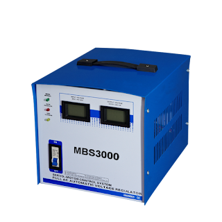
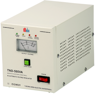
The linear regulator’s power dissipation for a given output and input voltage is directly proportional to its output current. So, typical efficiencies can be 50% or even lower. Efficiencies in the 90% range can be achieved by using the optimum components like a switching regulator. However, as compared to a switching regulator with the same output voltage and current requirements, the noise output from a linear regulator is much lower. Typically, higher current loads can be driven by the Automatic Voltage Regulator than a linear regulator. Follow us on Facebook
Wednesday, 1 December 2021

Working Principle of the Thermal Overload Relay

On the heat produced by the excessive overload current, a thermal overload relay works. To trip the motor circuit, the heat produced by the overload current is used. For the protection of DC motors of lower output rating or low-voltage squirrel cage induction motors, these are used mostly.

In motor starter circuits, the motor can be prevented from drawing excessive current by the function of a thermal overload relay. This current is harmful to motor insulation.

electronic thermal overload relay

It is connected either indirectly through current transformers or directly to motor lines. It stops the motor and de-energies the starter when excessive current is drawn.

Thermal Overload Relay Working Principle

It will be heated up gradually and draw more current from the line whenever the motor is overloaded. To protect the motor against sustained overloads, the overload relay is intended.

To mechanically operate the trip bar or make a contact with the trip circuit, the overload relay is installed on the motor control circuit. Thus in the event of excessive load, it shuts down the motor. The electronic thermal overload relay can also be preferred.

Bimetallic strips are present in it. To heat the bimetallic strips, the heat produced by the overload current is utilized.

electronic thermal overload relay

The strip remains straight under normal operating conditions. But, the strip is heated and bent under the action of the fault current, and the relay contacts separate.  Thus, the motor control circuit gets de-energized.

By an adjuster, the force needed to bend the bimetallic strips can be adjusted. To operate at different overload currents, it can be adjusted In other words.

Short circuit protection is not offered by the fuji electronic thermal overload relay as it takes sufficient time to open the contacts. Therefore with fuses, this type of relay is used in conjunction to provide short circuit and overload protection to the circuit.

Inverse time characteristics are present in these relays i.e. current increases and the tripping time becomes less as the overload. In trip class, these are rated. The period it will take to operate in an overload condition is specified in the trip class. The most common classes are 30, 10, 5, and 20. Follow us on Facebook

Monday, 22 November 2021

Get to Know about the Contactor’s Principle of Operation

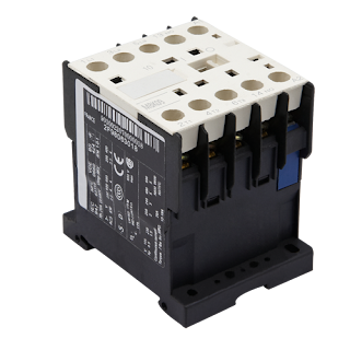
An electrical switching device is an electric contactor. For switching an electrical circuit off and on, it is used. It is a special kind of relay, but between a relay and the contactor, there is a basic difference. In applications where higher current carrying capacity is involved, the contractor is mostly used while for lower current applications, the relays are used. Usually, multiple contacts are featured by these devices. The contacts provide operating power to the load and are mostly normally open whenever the contactor coil is powered. With electric motors, Contactors are popularly used.

motor contactor

There are different contactors types, and their own sets of capabilities, applications and features are present in the various types. Ranging from voltage from 25VDC to thousands of volts and a few to thousands of amperes, Contactors can take over a vast range of currents. Furthermore, in various sizes, these devices come. Measuring up to a meter or a yard on one side, they are small hand-held dimensions to large sizes.

With high-current load, a motor contactor is most commonly used because of its capability to handle high power well over 100kW and current well over 5000 amperes. They produce arcs when heavy motor currents are interrupted. To control and reduce these arcs, a contactor can be used.

electric contactor

Contactor’s Principle of Operation

The contactor’s operating principle is very simple; the electromagnet is energized by the current flowing through the contactor. A magnetic field is created by the energized electromagnet. The contactor core moves the armature as a result of this. Between the fixed and moving contacts, the circuit is then completed by a normally closed (NC) contact. This contact allows the current to pass to the load through the contacts.

The coil opens the circuit and is de-energized when the current is stopped from passing through. The contacts of contactors can close and open rapidly. Thus, larger loads can be handled by them. Moving contacts may bounce as magnetic contactor is designed to rapidly close and open contacts, as they rapidly collide with fixed contacts. In many contractors, Bifurcated contacts are used to avoid bouncing. Follow us on Facebook

Tuesday, 2 November 2021

Working and Characteristics of an Electrical Fuse

A fuse is an electric/electronic or mechanical device, which is generally used to protect circuits from overloading, the excessive current which then makes sure the protection of the circuit. There are different electrical fuse manufacturer and types of fuses, but their function is the same. Here we will discuss its construction, working, and characteristics.

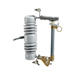
Meba SJC 36KV Cut Out Fuse

Working and Construction of a Fuse

A general fuse consists of a low resistance metallic wire that is enclosed in a non-combustible material. It is used for connection and installation in series with a circuit and device which then needs to be protected from short circuit and over current. If it is not done then in the absence of the fuse, circuit breaker, and arrester disconnector, the electrical appliance may get damaged as they are unable to handle the excessive current according to their rating limits

The thin wire inside the fuse melts whenever a short circuit, over current or mismatched load connection, occurs and it is due to the heat generated by the heavy current flowing through it. Therefore, from the connected system, it disconnects the power supply. Fuse wire is just a very low resistance component in the normal operation of the circuit and it does not affect the normal operation of the system connected to the power supply.

electrical fuse manufacturer

Characteristics of a Fuse

  • Breaking Capacity of a Fuse
  • Current Carrying Capacity of Fuse and its fuse
  • I2t Value of Fuse
  • Response Characteristic of a Fuse
  • Response Characteristic
  • Rated voltage of Fuse
  • Voltage Rating of Fuse

Packaging Size

On the amount of current flowing through its wire the speed at which the fuse blows rely on. The response time will be faster if the current flowing through the wire is higher.

For an overcurrent event response, the characteristic shows the response time. Ultra-fast fuses or Fast fuses are the types of fuses that respond rapidly to the current situation. In many semiconductor devices, they are used as semiconductor devices are damaged by overcurrent very rapidly.

electrical fuse manufacturer

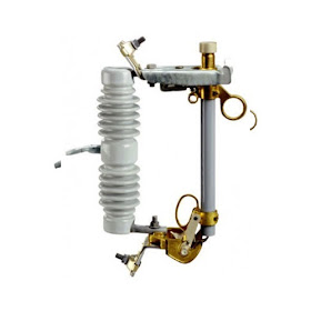
There is another fuse which is called a slow burn fuse. To the overcurrent event, this 24kv drop out fuse does not respond instantly but after several seconds of over-current occurrence, it blows. In motor control electronics systems such fuses found their application and it is because motors take a lot more current at starting than running. Follow us on Twitter

Exploring Cam Switches: Versatile Components for Electrical Control

Cam switches are essential components in electrical control systems, known for their versatility and reliability. These switches play a cruc...